


High Quality Link Emulator, Ideal for Krypto Link Emulation
Features / Benefits
- *Network Delay Emulator for serial data delay emulation & TELCO Latency Emulation
- * Bi-directional independent delay buffers per channel, Full Duplex
- * Supports Split Speed and Delay
- * Interfaces supported DS3, E3, STS-1, DS1/E1, TTL, HSSI, RS- 232, RS-422/449, RS-530, V.35, and X.21
- * Data Rates: 1.2K to 51.84Mbps
- * Network Simulation Delays of 5mS up to 4 Seconds in 1mS increments, each data path
- * Random Error insertion from 1x10⁻¹ to 1x10-12 BER
- * Burst Error insertion
- * BERT 511 generator and tester
* Timing Internal or from either port interface. Accepts external clock for synchronization of internal timing
- * Managed via serial port or web enabled GUI interface
- * Status LED's for each port allows ease of connection and trouble shooting
- * Internal 90-240 VAC auto sensing power supply
- * Sturdy 1U Metal Enclosure, Desk Top or Rack Mount
Description
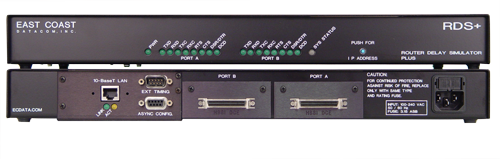
The Router Delay Simulator Plus or RDS+ Network Emulator allows users to test/stage critical DCE or DTE equipment for reliable network operation while simulating network delay times. The RDS+ provides a realistic simulation of physical network behavior with respect to time delays and bit errors. It supports user circuit rates up to OC-1 (51.84 Mbps) while providing delays from zero to a maximum of 8 seconds round trip. Both continuous random and burst errors are supported. The RDS+ is an ideal satsim satellite simulator.
By using the RDS+ in place of or in series with a real data link (WAN) a wide variety of error conditions can be introduced under controlled and testable conditions.
The RDS+ has two data port interfaces that support EIA-644(LVDS), RS-232, RS-422/449, RS-530, V.35, X.21, DS1/E1, TTL, HSSI, DS3, E3, or STS-1. The data interfaces can be mix and matched where applicable, such as V.35-to-RS-530 connection.
Data Clocking can be driven from various sources. It can be provided via the TX and/or RX clocks of the various data port interfaces. Clocking can also be provided from a programmable clock generator internal to the RDS+. An independent external timing source can be used to frequency-lock the internal timing generator via an external timing port on the back of the RDS+.
Data/Control-Lead Delay is programmable in either seconds or number of data bits. Delay may be specified independently to any value on each of the two bi-directional data paths. An option exists to include a control lead on some interfaces with the data delay.
The RDS+ can introduce Random and/or Burst errors into the data stream. These two error types can be used independently or in a combined fashion. The Random error rate is entered as a range of 1x10⁻¹ to 1x10-12 errors per bit. Burst errors are entered as duration and interval. The error burst duration is from 1ms to 4 seconds and the interval between bursts is from 1ms to 16seconds. The type of error introduced can be the compliment of the data bit, a forced 0, or a forced 1.
The RDS+ contains one BERT generator and one BERT tester. The generator and tester can be independently attached to either data port. When activated the BERT generator replaces the assigned data port data with a standard x9+x5+1 polynomial function to generate a pattern of 511 bits in length. When activated the BERT tester can monitor the data port in either a continuous or a windowed mode. The continuous mode is manually re-triggerable. The windowed mode can be set for a monitor window from 1 to 256ms.
The RDS+ supports digital loopback of either data port. Loopback, Data Delay, Error Simulation, and BERT can all be used simultaneously on a given port. Installation and operation is provided via an operator console port. This port is a RS-232 port that has been tailored for use with HyperTerminal that comes standard with most PCs. RDS+ status and configuration is displayed in real time via this interface. An optional 10Base-T web enabled GUI interface is available for the RDS+.
The RDS+ has a Power LED, one System Status LED and a set of status LED’s for each Port interface, which allow the user to visually confirm the presence of data and clock, and certain control or status signals. The RDS+ is designed with state of the art digital CMOS technology.
The RDS+ is housed in a sturdy 1U high metal enclosure which can be rack mounted. It is powered by an integrated 90-240V 50/60Hz power supply. The RDS+ has a one year warranty and a 24 hour turnaround on warranty repairs.
SPECIFICATIONS |
|
| Application | WAN Delay Emulator for interconnection of two devices, (e.g. terminal, modem, or other network or CPE with standard serial digital interfaces) located within proximity of each other while simulating clock generation, network delays, random and burst errors, and BERT capability |
| Simulation Delay Times | 5 milliseconds(mS) to over 4000 mS, in 1 mS increments, or from 4 bits to over 65,000 bits in 1 bit increments. 4 seconds each data path, 8 seconds round trip delays. |
| Capacity |
Two (2) data port interfaces |
| Data Rates | From 1.2K to 51.84Mbps |
| Data Port Interfaces | Available in EIA-644(LVDS), RS-232, RS-422/449, RS-530, V.35, X.21, TTL, HSSI, DS1/E1, DS3, E3, STS-1 |
| Clock Sources |
Internal, Stratum 4 or Locked to External, Data Port RX/TX supplied |
| Data Format |
Synchronous or Asynchronous |
| Delay Units | Specified in milliseconds or in bits |
| Random Error Rates | From 1x10⁻¹ to 1x10-12 |
| Burst Errors |
Burst duration from 1mS to 4 Seconds |
| Test Modes | Loopback, 511 BERT |
| Operator Console | RS-232 Async, 38.4kbs, (HyperTerminal recommended) *Optional web enabled GUI interface |
| Indicators | Power TXD, RXD, TXC, RXC, RTS, CTS, DSR/DTR, DCD for each user port |
| Power Source |
90-240VAC @10%, 50/60Hz, IEC Power Inlet, (2) 5mm Fuses |
| Environmental | Operating Temperature....32º to 122º F (0º to 50º C) Relative Humidity.............5 to 95% Non-Condensing Altitude............................0 to 10,000 feet |
| Dimensions | Height: 1.75 inches (4.44 cm), Width: 17 inches (43.18 cm), Length: 9 inches (22.86 cm) |
| Weight | 4.5 pounds (2.1 Kg) |
| Warranty | One Year, Return to Factory |
| Regulatory Approvals | UL 60950-1:2003, CAN/CSA-C22.2 No. 60950- 1:2003, FCC Part 15, EN55022:2006, ICES-003, Class A |
| Ordering Information | Part #: 175000 Model: RDS-PLUS, Base Unit Description: Router Delay Simulator - Plus Part #: 175030 Model: RDS-PLUS, GUI Description: Web enabled GUI interface Interfaces Available: |
|
129014, RS-232 DCE I/M, RS-232, DB-25 Female, DCE Interface Module(connects to DTE) 129032, RS-232 DTE I/M, RS-232, DB25 Male, DTE Interface Module(connects to DCE) 129010, V.35 DCE I/M, V.35, MR-34 Pin Female, DCE Interface Module(connects to DTE) 151038, V.35 DTE I/M, V.35, DB-25 Male, DTE Interface Module(connects to DCE) (Requires adapter Cable PT# 712005) 129028, V.35 DTE I/M, V.35, MR-34Pin Male, DTE Interface Module(connects to DCE) 129011, RS-530 DCE I/M, RS-530, DB-25 Female, DCE Interface Module(connects to DTE) 129029, RS-530 DTE I/M, RS-530, DB-25 Male, DTE Interface Module(connects to DCE) 129012, RS-422 DCE I/M, RS-422/449, DB37 Female, DCE Interface Module(connects to DTE) 129030, RS-422 DTE I/M, RS-422/449, DB-37 Male, DTE Interface Module(connects to DCE) 129013, X.21 DCE I/M, X.21, DB-15 Female, DCE Interface Module(connects to DTE) 129031, X.21 DTE I/M, X.21, DB-15 Male, DTE Interface Module(connects to DCE) 129085, T-1 I/M, T-1 Interface Module, 1.544 Mbps, RJ-48 & DB-15 Female 175097, E-1 I/M, E-1 Interface Module, 2.048 Mbps, 75 ohm BNC 151028, HSSI DCE I/M, HSSI, SCSI-I 50 Pin Female, DCE Interface Module(connects to DTE) 151043, HSSI DTE I/M, HSSI, SCSI-I 50 Pin Female, DTE Interface Module(connects to DCE) 175020, DS3 I/M, DS3 Interface Module, 44.736 Mbps, 75 ohm BNC 175021, E3 I/M, E3 Interface Module, 34.368 Mbps, 75 ohm BNC 175022, STS-1 I/M, STS-1 Interface Module, 51.840 Mbps, 75 ohm BNC 175040, EIA-644 LVDS DCE I/M, EIA-644 LVDS, DB-25 Female, DCE Interface Module(connects to DTE) 175045, EIA-644 LVDS DTE I/M, EIA-644 LVDS, DB25 Male, DTE Interface Module(connects to DCE) |
|