


Features / Benefits
- Interface - 50 Ohm BNC
- Input - Single 10 Mhz Sine Wave
- Output - Four Ports, 10 Mhz Square Wave
- One In, Four Out Converter / Splitter
- Low Signal Level Detector Circuit
- 110/220VAC or DC Voltage Supply Option
- CE Approved, RoHS Compliant
- Sturdy Aluminum Enclosure
Description
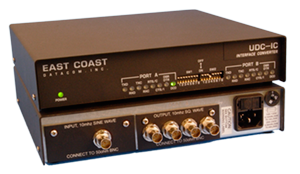
The UDC-IC 10 MHz Clock Converter is intended to accept a standard 10 MHz sinusoidal reference signal, convert it to a typical 5V TTL-level output, and distribute this output to 4 separate devices over individual coax cables.
Each cable driver element is designed to launch a signal through a 50-ohm series termination. With a single high-impedance load at the end of the 50-ohm cable, the load will see the incident signal as a square wave. Reflections back to the source are absorbed for the most part by the series termination in combination with the low-impedance driver.
If the 10Mhz Input Sine Wave is within tolerance, the front panel CLK and DCD LED Indicators will be green. If the 10Mhz Input signal is out of tolerance the CLK and DCD LED indicators will not be illuminated.
The 10MHz receiver card is also equipped with a low signal level detector circuit that cuts off the converter to prevent compromised clock signals from reaching downstream equipment. This will normally happen when the input signal falls below the minimum +5 dBm level. The front panel indicator, DCD will be on when an input signal of sufficient level is seen, and off when the cut-off circuit senses a low level or absent input.
The UDC-IC 10Mhz Clock Converter is simple to use by connecting a 50-ohm Coax Cable to the 10Mhz Sine Wave INPUT marked PORT B located on the rear panel. Then connect from one to four 50-ohm Coax Cables to the OUTPUT ports 1-4 located in PORT A.
The front panel LED marked PWR, CLK and DCD should be illuminated. If the CLK and the DCD LED’s are not illuminated, the UDC-IC 10Mhz Clock Converter is not receiving a good 10Mhz Sine wave.
The UDC-IC has a three year warranty and a 24 hour turnaround on warranty repairs
SPECIFICATIONS |
|||||||||||||||||
| Application | Interconnection of 10 Mhz systems sine wave to square wave clock distribution | ||||||||||||||||
| Capacity | One Input, Four Outputs | ||||||||||||||||
| Rear Panel Data Interface | One: 10Mhz Sine Wave Input Four: 10Mhz Square Wave Outputs | ||||||||||||||||
| Data Format | Data Transparent at all Data Rates | ||||||||||||||||
| Data Rates | 10Mhz | ||||||||||||||||
| Front Panel Indicators | POWER and each data channel has DCD and CLK | ||||||||||||||||
| Surge Protection | Main power supply | ||||||||||||||||
| Power Source | AC Mains: 100-120 to 200-220VAC @10%, 50/60Hz, 0.16/0.08A, external 110/220 volt select switch, IEC Power Inlet, (2) 5mm Fuses DC Mains: DC Voltage, Input Range of -36 to -72vdc Current Draw at 48vdc: 75ma @ 3.6watts |
||||||||||||||||
| Environmental | Operating Temperature....32º to 122º F (0º to 50º C) Relative Humidity.............5 to 95% Non-Condensing Altitude............................0 to 10,000 feet |
||||||||||||||||
| Dimensions | Height ....... 1.75 inches (4.44 cm) Width ........ 9.00 inches (20.86 cm) Length ...... 9.00 inches (20.86 cm) |
||||||||||||||||
| Weight | 3 pounds (1.364Kg) | ||||||||||||||||
| Warranty | Three Years, Return To Factory | ||||||||||||||||
| Regulatory Approvals | UL 60950-1:2003, CAN/CSA-C22.2 No. 60950- 1:2003, FCC Part 15, EN55022:2006, ICES-003, Class A | ||||||||||||||||
| Ordering Information |
Main Unit Part Number: 190000 Model: UDC-IC Description: UDC-IC Interface Converter, 110/220VAC
Optional 1U Rack Mount Chassis Part Number: 204000 Model: UDC-IC Rackmount Description: Rackmount UDC-IC Main Unit, 110/220VAC
|
||||||||||||||||
| Included with each unit: | 1) Operations Manual 2) Grounded Power Cord |
||||||||||||||||
| Optional Accessories | 1) Spare Data Center Fuses A) 160ma Fuse, Qty (2) Part # 714000 B) 80ma Fuse, Qty (2) Part # 714001 |
||||||||||||||||